
Bending Tooling
Bossray offers rotary draw tube bending die sets with the best fit and finish in the industry.
We use proprietary metallurgy for shock resistance and long die life, as well as the most durable mandrel linkage available with the toughest “snap-back” system for production tube bending.
We are also proud to sell the only wipers with fully machined precision feathered edges.
Bossray has a long history of innovation in both the design and manufacturing of rotary draw tube bending die sets.
- Design and Installation
- Correction
- Features and Options
- Related Products
- Wipers
- Tool System
The Design And Set Up Of Tooling For Rotary Draw Bending
1. BEND DIE
✔Hardened tool steel or alloy steel, heat treated and nitrided
✔Clamp insert is secured with cap screws and dowel pins
✔Drive key must be parallel to clamp insert
✔Bore should have a slip fit over centering ring or spindle
Note: Bend dies may have special tube grooves with captive lip or Empty Bending
2. CLAMP DIE
✔Hardened tool steel or alloy steel, heat treated and nitrided
✔Preferable length is 3 x tube O.D.
✔Tube groove is grit blasted or may be serrated if less than preferred length
✔With tube held in bend die, advance clamp die and adjust for vertical alignment.
✔Adjust for parallel contact with entire length of clamp
✔Adjust for pressure
3. PRESSURE DIE
✔Alloy steel and nitrided
✔Tube groove must be parallel to back of die
✔If follower type pressure die is used, length equals 180 degrees + 2 O.D.
✔If a boosted system is used, groove should be grit blasted
✔With tube clamped to bend die, advance pressure die and adjust for vertical alignment
✔Start with minimal pressure and increase as required in small increments
4. MANDREL
✔Type of mandrel and number of balls indicated by Tooling Selection Guide
✔Aluminum/Bronze, chrome, or Kro-Lon mandrels for ferrous tubing. Only chrome mandrels for non-ferrous
✔Gain best results with most mandrels when shank projects a small amount past tangent (bend and try)
✔Lube I.D. of each tube
5. WIPER DIE
✔The Tooling Selection Guide indicates when a wiper may be required
✔Push tube over properly located mandrel and bring clamp and pressure dies up to bending position
✔Slide wiper along tube as far as possible into bend die then secure to holder
✔Unclamp pressure and clamp dies, tip of wiper should be “very close” to tangent
Corrections For Poorly Bent Tubes
After the initial tooling set-up has been made, study the bent part to determine what tools to adjust to make a better bend. Keep in mind the basic bending principle of stretching the material on the outside radius of bend and compressing the material on the inside of the bend. Make only one adjustment for each trial bend unless the second adjustment is very obviously needed. Avoid the tendency to first increase the pressure die force rather than adjust the wiper die or mandrel location. Start with a clean, deburred and lubed tube with the elongation properties sufficient to produce the bend. Note: There are certainly other corrections that could be made for the following problems. These illustrations are a few examples of how to “read” a bend and improve the tooling set-up.
Tube Bending Die Set Features & Options
We offer standard dies and die sets for most tube- and pipe-bending machines:
✔Bend die with precision-machined inserted clamp
✔Reversible for left-hand and right-hand mounting
✔Single keyway
✔Lifting holes for bend dies larger than 8 inches (203mm) in diameter
✔Reversible clamp die with T-key or hanger bracket
✔Reversible pressure die with hanger brackets
✔Non-interlocked
✔Zero-lip die cavities
✔Smooth or V-Type (fine) serrated clamp cavities
✔Proprietary metallurgy and case-hardening for shock-resistance and durability
Options for standard die sets:
✔Double-inserted bend die
✔Double keyway and closed-end keyway
✔Precision posthole shoulders for mounting to tie-bar
✔Interlocked
✔Captive-lip die cavities
✔Carbide grip coating, or aggressive serrated clamp cavitie
Stackable die sets (for multi-bend operations):
✔Includes all features and options of our standard tube and pipe-bending die sets
Inter-die locating keys and hubs
Basic Mandrels And More
Tube bending has come a long way since wet-packed sand cerrobend or cable mandrels.
In addition to the basic mandrels described below, Bossray has designed these and many other specialty hybrid materials: hydroforming, waveguide, tube-within-a-tube, bend-on-a-bend, sizing, bullet-nosed, plastic, and sheathed materials.
Among the many factors which influence the type of mandrel selection and number of balls, these are the most important considerations:“D” of Bend (center line radius ÷ tube O.D.)
✔Wall Factor (tube O.D. ÷ wall)
✔Ovality and wall thinning requirements
✔Tubing materials
✔Cosmetic considerations
✔Size and location of weld flash
3 products found

The proper style of bend dies to be used will be indicated by such factors as tube O.D. x C.L.R. bender size, degree of bend.

There are distinct differences from what would be considered sets of bender tooling and a tooling system.

Bossray Rotary draw bending is by nature more involved and complicated but subsequently the most versatile.
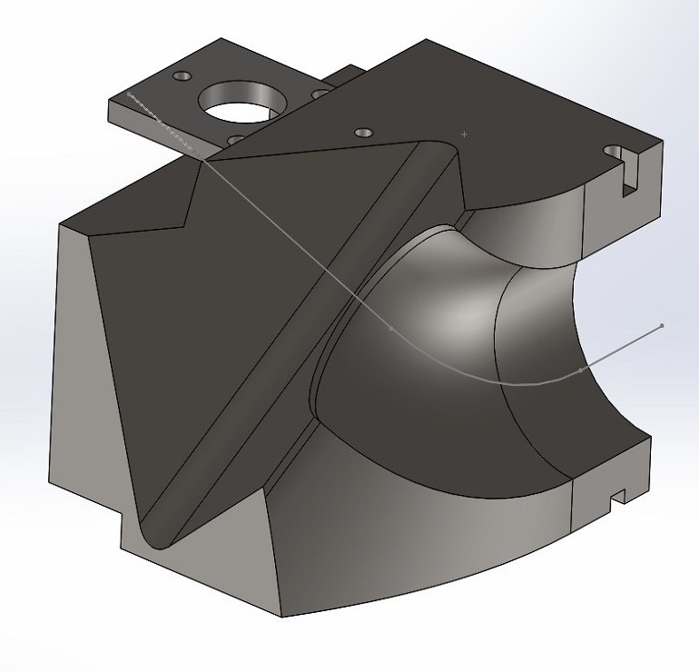
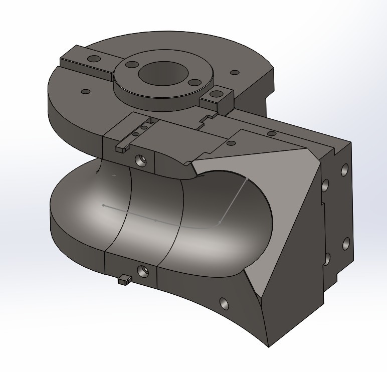
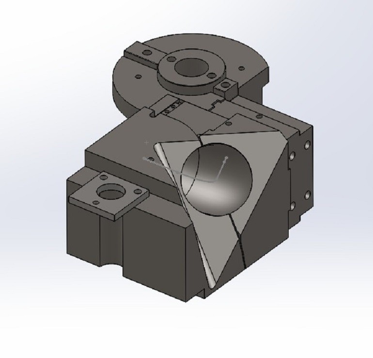
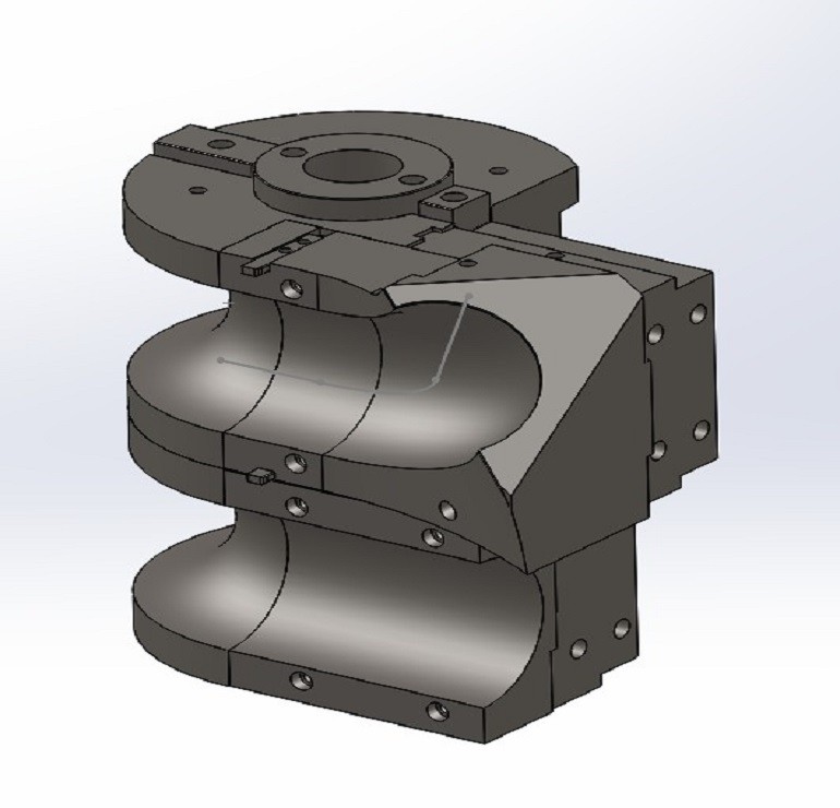
Bender Tooling Systems
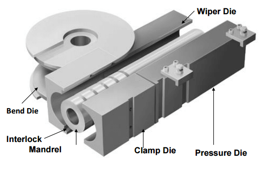
TYPICAL ROTARY DRAW BENDING SET
THE SET CONSISTS OF:
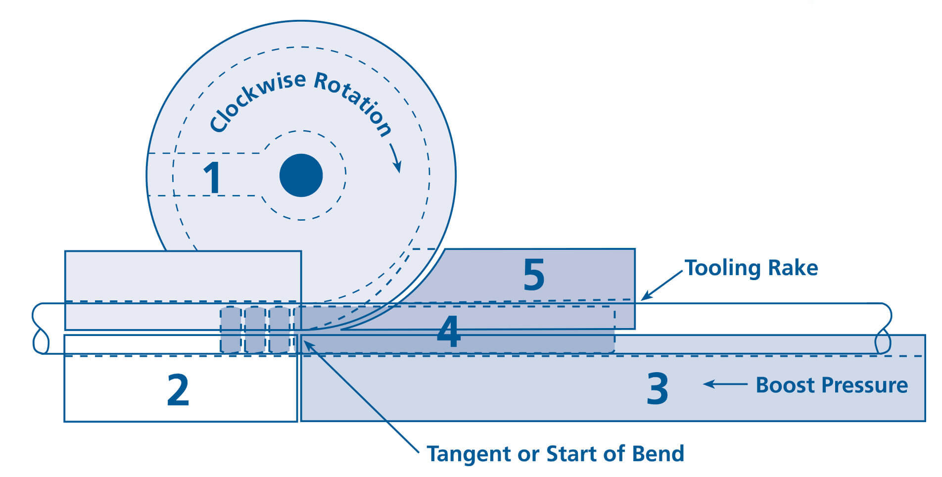
The Bend Die…Rotates with the tube forming it to the correct radius.
The Clamp Die…Grips the tube against the bend die to prevent slipping.
The Pressure Die…Moves forward with the tube forcing it to conform to the radius of the bend die.
The Mandrel…Internal to the tube supports the tube at tangent prevents collapse of the tube.
The Wiper Die…Rides between the tube and the bend die controls the compression side on the bend.
STRAIGHT CLAMP DIE
COMPOUND CLAMP DIE
GUSSETED SPOOL BEND DIE WITH COMPOUND GRIP INSERT
WITH ADDED COMPOUND CLAMP
Wipers
Bossray leading inserted wiper die is our most popular product.
Over the past twenty years, we have perfected the design and manufacture of our inserted wiper dies for tube bending, and no one else comes close to our quality, price, and speed of delivery.
We also manufacture traditional “aircraft-quality” square-back solid-body wiper dies plus we have a resharpening service for these tools (including those made by our competitors).
Square-back solid-body wiper dies are excellent for high-pressure tube-bending jobs that require the wiper to be set at zero-rake.
However, they are relatively costly to purchase and then recondition as they wear.
Whether inserted or solid, our wiper dies for tube bending have a fully machined feathered edge.
Unlike our competitors, there is no manual honing or sanding of the feathered edge.
Bossray precision machines this essential attribute of the wiper die.
With tube bending equipment, do not settle for less.
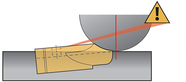
Understanding Wiper Set-up with Standard-Style Inserts
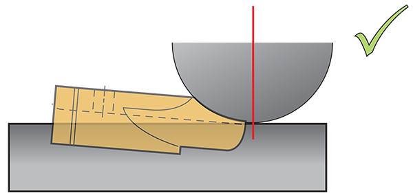
Standard-Cut Wiper Proper Positioning
Wiper tip raked slightly to ensure tip will not become pinched between tube and bend die. Full contact with bend die for maximum support.
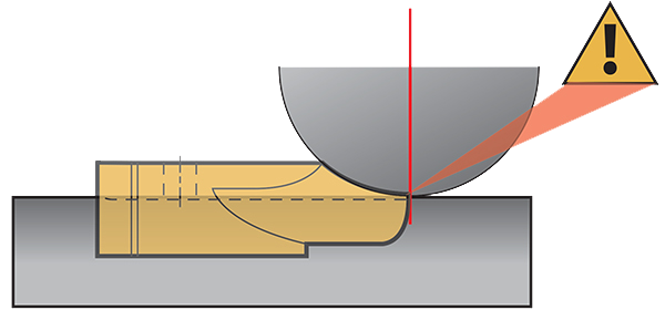
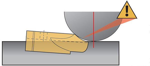
Standard-Cut Wiper Zero Rake Angle
Wiper tip may become pinched between tube and bend die. This may damage the tip or lead to imprint on tube.
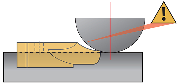
Standard-Cut Wiper Zero Rake Angle Pulled back
No support to the heal of the wiper insert will allow the wiper tip to flex during bending. Wrinkles may form.
Understanding Wiper Set-up with “Aerospace” (Aero) Inserts
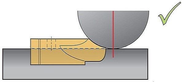
Aero-Cut Wiper Proper Positioning
Very little or no rake angle. Full contact with bend die for maximum support.
Aero-Cut Wiper Negative Rake to bring tip closer to tangent
Back of wiper insert may drag against tube causing marking. This may also lead to clamp slippage and wrinkles.
Aero-Cut Wiper Too much Rake Angle Too close to tangent
No support to feathered edge of wiper insert will lead to wiper tip failure.
We're Here for You Anytime, Anywhere
We are at your service anytime, anywhere
Bossray provides professional services throughout the pre-sales, sales and after-sales processes to solve various problems for you.

subscription
Please send your message to us
Bossray provides you with more professional solutions and services, contact us now
- *Name
- *Tel
- *Title
- *Content